905 nm application teardown
Anatomy of a 905 nm laser rangefinder
A rangefinder is four parts and one optical budget. Pick a part from the bill of materials, drop it on the module, and read the parameters that decide whether the design reaches 10 m or 2 km - each one with the catalogue parts that carry it.
- 1Pick a part from the bill of materials.
- 2Drop it on the module, or just click the card.
- 3Read its job, its parameters and the part numbers behind them.
Bill of materials
Every part, one optical budget. Drag a card onto the photo, or click it - the panel beside it fills in with that part's parameters.
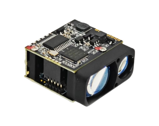
Drag a part here or click a card in the bill of materials
Front face, two optical windows: transmit on the left, receive on the right. Driver board on top.
Component positions are a teaching diagram, not an assembly drawing: the placement and the exploded view are indicative. Parameter values are those of the linked specification.
Every part, parameter by parameter
The same numbers the interactive view shows, in tables you can read, search and quote.
905 nm laser diode Transmitter
Emits the ranging pulse. Peak power, pulse width, divergence and emission timing together decide how far the system reaches and how much power it burns.
| Peak wavelength | 905 nm (895 - 915 nm) |
|---|---|
| Peak output power | 40 - 600 W |
| Pulse energy @ 100 ns | 4 - 30 uJ |
| Number of emitters | 3 - 9 stacked |
| Aperture size (w x h) | 110 x 30 um |
| Beam divergence, FWHM | 9 x 25 deg bare | 9 x 6 deg FAC |
| Pulse width | 1 - 100 ns (max 100 ns) |
| Duty cycle, max | 0.1 % |
| Repetition rate | up to 10 kHz |
| Operating current | 12 - 55 A |
| Operating voltage | 12.6 - 80 V |
| Package | TO56 | metal stack | bare die |
Avalanche photodiode Receiver
Sets how faint an echo the system can still see. Sensitivity only means something together with responsivity, gain, dark current, bandwidth, bias stability and the receive aperture.
| Response spectrum | 400 - 1100 nm |
|---|---|
| Wavelength | 905 nm |
| Active diameter | 230 um | 500 um | 16 elements |
| Responsivity | 80 A/W @ M=100 |
| Response time | 0.5 ns |
| Dark current | 0.4 nA @ M=100 |
| Total capacitance | 1.0 pF @ M=100 |
| Optimum gain | 100 |
| Reverse breakdown voltage | 100 - 200 V |
| Voltage temp. coefficient | 1.1 - 1.4 V/C |
| Optical filter | 905 nm spike filter |
| Package | TO-46 | LCC1 / LCC2 ceramic | linear array |
Optics Optical path
Transmit optics set the spot size, the divergence and the eye-safety geometry. Receive optics set how much of the echo ever reaches the APD.
| Optical channels | 2 (transmit + receive) |
|---|---|
| Transmit beam, bare emitter | 9 x 25 deg FWHM |
| Transmit beam, FAC | 9 x 6 deg FWHM |
| Aperture size (w x h) | 110 x 30 um |
| Receive aperture / focal length | Set by your module design Set by your design |
| Receive filter | 905 nm spike filter at the detector |
| Windows on the front face | 2 |
Drive and timing electronics Electronics
Sets the pulse shape - width, rise time, jitter - and the receive bandwidth. Both feed straight into distance resolution and into the smallest pulse you can use.
| Peak pulse current | 70 A |
|---|---|
| Pulse width | 50 ns - 1 us adjustable |
| Repetition rate | 1 kHz - 30 kHz adjustable |
| Rise time | 7.5 ns typical |
| Fall time | 12 ns typical |
| Supply voltage | 12 V DC |
| Laser drive voltage | 1 - 50 V DC |
| Control interface | Internal trigger / external TTL |
| Factory default | 100 ns @ 3 kHz, internal trigger |
Every parameter value on this page is pulled from the catalogue record that renders the linked product page, so the two cannot disagree.
Parts behind these parameters
Every figure below is read from the same catalogue record that renders the product page. Nothing on this page is retyped.
Transmit chain
Pulsed 905 nm sources from 40 W to 600 W, in TO56, metal stack and collimated packages.
Receive chain
Silicon APDs at 905 nm: two active areas, two package families, plus a 16-element array.
Drive and timing
A 70 A nanosecond driver board that already has the timing generator on it, so the first prototype does not need a custom board.
This module is the 905 nm / pulsed / rangefinder scenario
Run the selector with application = rangefinder, wavelength = 905 nm and output = pulsed and it returns the transmit chain listed below. The teardown shows what those parts become once they are assembled, aligned and driven.
The receive side is the hard half
Send us the target, the range and the size limit. We come back with a transmit chain, a detector and the loss budget between them.